New to CNC? Get started quickly with Cut2D
Cut2D is an easy to use vector drawing and editing software package with powerful 2D machining strategies for CNC routing, milling or engraving.
Cut2D - Produce 2D patterns with profile, pocket, drill & inlay toolpaths
Cut2D provides a powerful but intuitive software solution for cutting parts on a CNC router and includes tools for 2D design and editing and efficient 2D toolpath calculation
The ‘Desktop’ edition is designed for small CNC machines, aimed at hobby or non-production environments, while the 'Pro' edition includes unlimited job and toolpath size, true shape nesting & job set-up sheets, ideally suited to a production environment.
Will Cut2D work with my CNC machine?
Unleash your creativity with Cut2D
2D Import & Editing
2D Import & Editing

2D Toolpath Options
2D Toolpath Options

Easy for Complex Projects
Easy for Complex Projects

Customize & Control
Customize & Control

Cutting Larger Projects
Cutting Larger Projects
Instant Preview Updates
Instant Preview Updates
Desktop or Pro, which one is right for you?
If your CNC machine bed size is 24” x 24” or smaller, Cut2D Desktop is right for you.
If you have a larger machine and you are looking to add production tools like nesting, templates and gadgets to your workflow Cut2D Pro is the one for you.
| Desktop | Pro | |
|---|---|---|
| Work area | 24" x 24" | Unlimited |
| True shape nesting | No | Yes |
| Merging toolpaths | No | Yes |
| Toolpath templates | No | Yes |
| Gadgets | No | Yes |
| Job Setup Sheets | No | Yes |
| Keep-out Zones | No | Yes |
| Array copy toolpath | No | Yes |
Over 100 Cut2D compatible CNC projects available for free
What's new in the latest release?
V12 brings a refreshing new user interface designed to enhance usability and reduce mouse miles, as well as adding some exciting new features and enhancements including:
- Drawing in the 3D View
- Orthographic View Mode
- View Control
- Keep-out Zones *Pro only
Drawing & Layout Tools
Drawing & Layout Tools
Drawing & Layout Tools
Vector Shape Creation
The software has a comprehensive set of drawing tools to let you easily create vectors from scratch or add to imported data. These include options for creating standard shapes (circle, ellipse, rectangle, polygon and star) along with line, curve and arc drawing tools.
There is also a powerful tool to create vector textures for panels and backgrounds. These tools can be controlled using typed input to create exact sized objects or can be used dynamically with the mouse to sketch your artwork. The tools also take advantage of the 'snapping' to let you use points on existing objects to 'snap' onto when you are drawing vectors.

Picture Editing & Cropping
With the ability to import bitmaps into the software, you can further edit imported images using the 'Edit Picture' tool, this allows you to adjust the visual properties of a selected bitmap, enabling you to adjust the contrast, brightness and gamma of any selected image.
Borders of different sizes and radii can also be added to bitmaps for aesthetic purposes. Bitmaps can also be made black and white. The software also has the ability to crop images to any given vector allowing you to remove parts of the image you are not interested in.
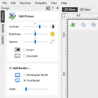
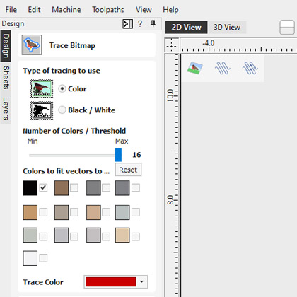
Image Tracing (Vectorization)
Image tracing also known as vectorization allows you to take an imported image such as a scanned drawing, graphic design or photo and to convert colors in that to vector outlines. These outlines can then be used as part of your design to create toolpaths or to generate 3D shapes using the modeling tools.
The software will import many file formats including jpeg, bitmap, gif, png, tif, it will also extract images from a PDF file.
Advanced Text Tools
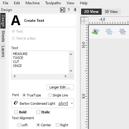
The 'advanced text' tools let you access true type or open type fonts on your PC to create text outlines for your design. In addition, the software comes with a selection of specialist single stroke / stick engraving fonts for efficient machining when making things like badges or small signs.
When creating text you are able to see live feedback of the text that you create and edit. The text can be controlled using automatic sizing and layout options.
There is an inbuilt spell checker where errors will be underlined in red, you are able to locate the correct spelling as well as having the ability to add words to the software’s dictionary too!
There are also editing tools for fitting text to a curve and interactive text arcing and spacing (kerning) where the text maintains formatting, allowing you to easily make edits after the text has been created. This text can be dragged dynamically along a curve so you can perfect the placement of your text.
Import 2D Data
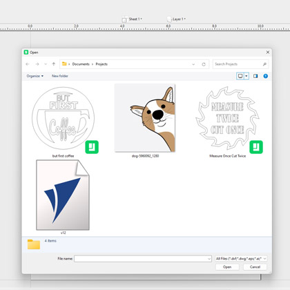
Data can be imported from a huge range of other design programs using a variety of industry standard file formats. These include DXF, EPS, AI, SVG and SKP (SketchUp) as well as PDF files. Once imported, the program has a wide range of tools to make working with this data as efficient as possible.
A very important set of tools are those used to identify duplicate vectors and identify and re-join open vectors. These tools can save an great deal of time when working with poor quality data to get it ready to machine. As well as importing vectors from other programs the software also offers the ability to export your data in either DXF, EPS or AI file formats. This feature is very important if you need to share data with a customer in order that they can use it to plan a layout or installation.
Basic Dimensioning
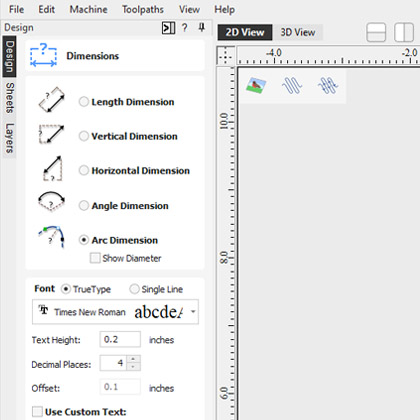
The dimensioning tools allows you to create a variety of different types of measurements on your drawing. These can be oriented in any direction or fixed horizontally or vertically. There are also options to add angular and arc dimensions. You can control the text height, font number of decimal places and position for each one.
Dimensions can be snapped to vectors, guidelines and the corners or mid-points of each side of your work area. As well as importing vectors from other programs the software also offers the ability to export your data in either DXF, EPS or AI file formats. This feature is very important if you need to share data with a customer in order that they can use it to plan a layout or installation.
Vector Transform & Editing
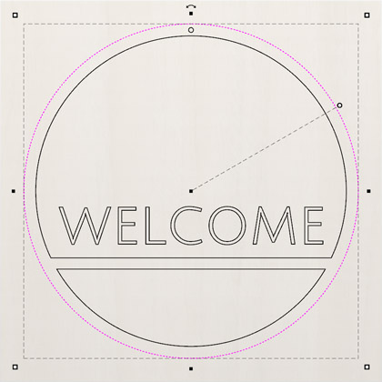
Whether your design vectors have been created in the software or imported you have a large choice of editing options to prepare your part for toolpath creation or modeling. Vectors can be easily scaled, moved, mirrored, distorted, grouped, welded, trimmed, filleted, extended, offset, smoothed and joined together.
As with the drawing tools you either have precise control over the editing values adjust the vectors very accurately or can use the mouse to dynamically make adjustments until your layout looks correct.
Vector Layout
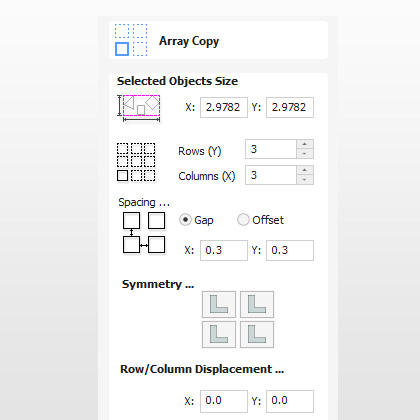
In addition to the editing tools the software also has tools to let you layout parts either in a rectangular array to create a grid of objects or in a circular array to create symmetrical layouts around a centre point. When laying out a grid you can adjust mirroring options and shift alternate rows and columns to make more complex layout patterns.
Vector shapes can also be pasted along the path of another vector by specifying the distance between each copy or just fitting a specific number on the guiding object.
Layer Management
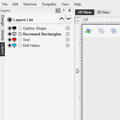
The layers are a very efficient way to keep your 2D data organized, one of the main uses is to allow you to temporarily hide data you were not currently working with. Layers could also be used to group vectors you might be using to model related shapes in a 3D design to make it simpler to work on a small part at a time.
The ability to associate toolpaths with specific layers and types of data means you can create toolpath templates which can be assigned to other parts that share the same layer structure. This is particularly powerful for applications like cabinet making where different designs can be automatically machined once a template has been set-up.
Multi Sheet Support
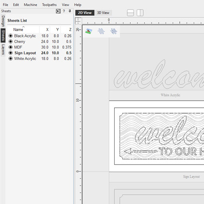
Not only can you organise your design onto layers but you can also make use of multiple sheets in your projects to help manage and organise your work on a per sheet basis when working with multiple materials in your designs. Each sheet can have it's own dimensions and settings, making it an ideal solution for when you are working on a project that requires multiple materials.
The sheets tab lists all of the current sheets and allows you to create, update and delete them. You can create sheets of different sizes and thicknesses as well as having the ability to control the material appearance for each sheet to better visualize your toolpaths as part of the overall project. All sheets within a project can be managed individually or collectively, making it simple to resize or update a specific selection of sheets.
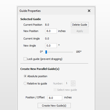
Rulers, Snap Grid and Guidelines
Rulers, snap grid and guidelines all help to make vector drawing and 3D part layout much simpler. These options can be switched on / off as required. When combined with snapping options that automatically detect and snap the cursor to key regions on a design these tools make it easy to create very accurate part.
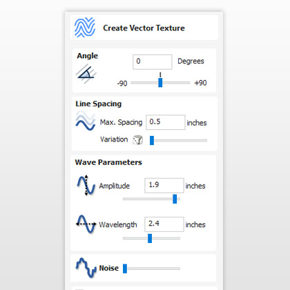
Create Vector Texture
Repeating vector patterns can be quickly created using the 'create vector texture' tool. It's easy to modify the settings to create an infinite number of variations from regular wave patterns through to uneven natural looking grain lines.
These vectors can be machined using the profile and texture toolpaths to create decorative wavy texture panels along with wood-grain and sand-blast effects. These can also be projected onto a 3D surface to add even more variation.
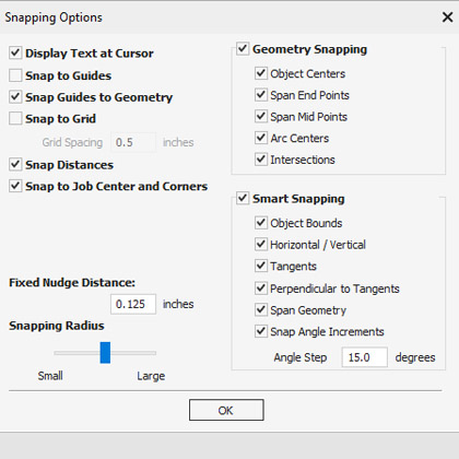
Smart Snapping
This allows you to snap to lines and extensions, which don’t necessarily exist as geometry. It reduces the need to create construction geometry, and would be helpful in aligning vectors or nodes.
Vector Validator
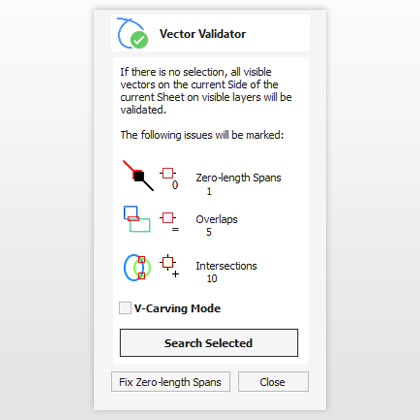
The vector validator is intended to help find issues with contours after file imports that are stopping tool-path creation such as overlapping contours or intersections. It also indicates zero-length spans.
Trim Objects to a Vector Boundary
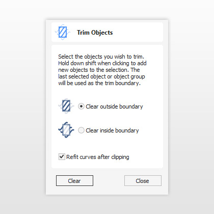
The trim tool allows you to simultaneously trim all the objects inside or outside of a selected area. This makes it very easy and quick to create textured areas or patterns within a specific boundary.
Machine Parts on Two Sides
Machine Parts on Two Sides
Machine Parts on Two Sides
Job & Material Setup
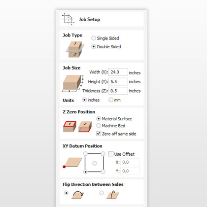
In the job set-up dialog, you can pick whether you want to create a single-sided, double-sided or a rotary job. You can change that, retrospectively. Define how you want to flip the material for double-sided projects from the job set-up dialog. This influences the positioning of the vectors and models so that geometry on each side is created in the appropriate positions relative to the opposite side.
Toolpaths
Toolpaths
Toolpaths
Material Setup
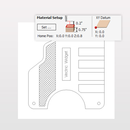
Referencing the software to how your CNC will be setup is one of the most important elements of the process. A summary of the material set up is displayed at the top of the toolpath tab allowing you to quickly check the settings before you start calculating toolpaths. Any of these values can be easily adjusted to change the tool reference for its X,Y or Z zero location, move the position of a model in the material, adjust the position where your machine starts from or specify distance to ensure the tool lifts above any clamping that is being used.
2D Production Profiling
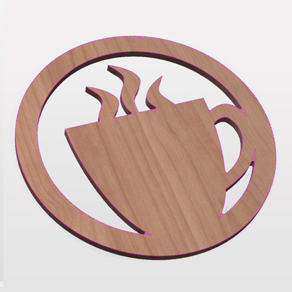
Using the profiling toolpath strategy, objects can be cut out quickly and efficiently. Simply select the vector shapes you wish to profile, select the tool from the tool database and the software will do the rest. The profiling automatically offsets for the tool radius and sorts nested shapes to ensure that inner shapes such as the center of a letter 'O' are cut before the outer shape (so parts are not released from the material before they are cut).
Full control of cut direction is offered along with either automatic or manual control of tool entry point for each shape. Profile machining includes production cutting options that ensure parts can be held in place and accurately machined with high quality edges and corner detail. - 3D tabs for smoother profiling plus advanced options for automatic positioning to hold parts in place when machining - Lead in / out and overcut distance to prevent dwell marks appearing on components - Advanced ramp options for controlling how the cutter enters the material, reducing heat build-up and cutter wear - Profile around the outside / inside of open shapes - Sharp internal and external bevelled edges and corners - Last pass allowance Cut-outs can be done in multiple passes depending on the maximum cutting depth of the tool used and a positive or negative allowance can be specified to either 'under cut' or 'overcut' the shape if required.
The number of passes on a cut can be edited very precisely to allow very thin final cuts or to individual add or remove particular cut depths. A separate last pass allowance can be specified for the last pass in a profile toolpath. If this allowance is given, then all but the last pass will be over-cut by the specified allowance with the final pass being the only pass which cuts to the actual edge of the part. This can significantly improve the finish on the cut-edge. The ability to specify that square corners are required is another powerful feature. This is often used when profiling with a v-bit tool, where with a conventional toolpath the tool will 'roll' round a sharp external corner leaving a radius on the top of the chamfer created by the tool, with the 'square corners' option an angular chamfer will be created instead. The profile toolpath is probably the most important toolpath option available. It is used for some of the simplest and also the most complex things you may do with your CNC. The software has been structured to let you customize whether you just want simple options for quick cut-outs or whether you want to access more advanced features to control cutting on particular material. This allows both new and experienced users to decide how much information they need to be presented with when creating this frequently used function.
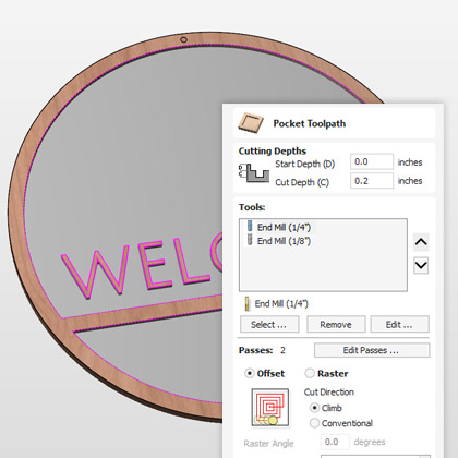
Fast and Efficient Pocketing – optimizes use of multiple tools
The pocket toolpath makes machining the material away from inside a vector shape efficient and easy to achieve. Just select all the vectors defining the shapes you want to cut and the program will sort the vectors to identify islands automatically and offset the boundaries for the selected tool radius. The 2D pocketing toolpath has the ability to control pass depths very precisely, either automatically based on the tool settings or where required the user can specify any combination of depths for a particular tool. Either climb or conventional cutting directions can be specified in order to produce the best edge finish for your selection of material and cutter. The tool can also be ramped into the job to reduce cutter stress when entering the material.
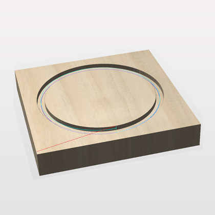
Helical Arc Support
Output helical arcs in a way that your machine understands. Makes for smoother cuts and smaller file sizes. Helical arcs are like regular arcs when viewed in 2D but where the start z and the end z differ. They are typically found in toolpaths where ramping occurs.
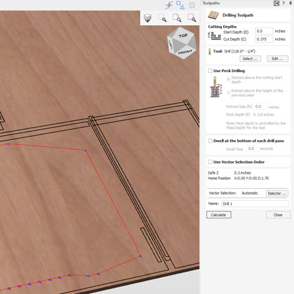
Drilling Toolpath
Whether you are drilling a single hole or hundreds, just select the vectors representing the holes and the software will drill the center of each vector to the specified depth. The grouping feature makes it easy to associate all vectors for a particular toolpath strategy together so only one needs to be selected. The tool database includes a dedicated drill tool type so that the true tool geometry can be seen in the toolpath previews. As well as a single Z plunge you also have the option to activate peck drilling, which drills to a specified depth, retracts the tool to clear the chips, drills down to the next step, retracts the tool and so on until the required finish depth is reached.
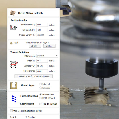
Thread Milling Toolpath
The thread milling toolpath enables you to machine holes for standard size screws in metals, woods, and acrylics, and is also useful for the creation of decorative wood fasteners. The thread milling toolpath has the option to create both internal and external threads, for example if you wanted to create a cavity to screw something into or if you wanted to create an exterior thread on something like a bolt!
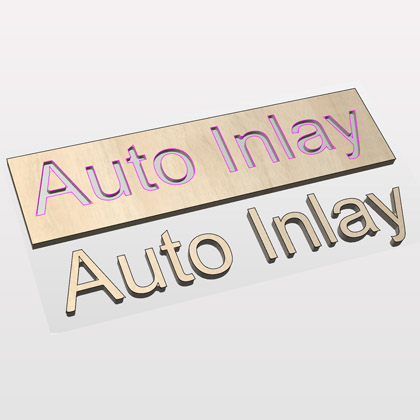
Auto-inlay Toolpaths
The auto-inlay toolpath options calculate profile cut-out and pocketing toolpaths for parts that need to be assembled to make inlays and inserts. - Automatic cutter radius compensation on corner regions to ensure male shapes will fit into female pockets or cavities - Allowance option to ensure a sufficient 'gap' is created to allow parts to fit together - 4 different Inlay options that are designed to make machining inlays very simple and straightforward (straight, stepped, pocket and hole) - Ideal toolpath option for sign makers, woodworkers, plastic and solid surface fabricators who need to cut parts that fit closely together.
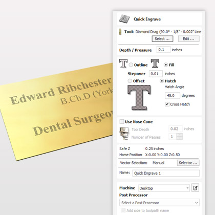
Quick Engrave for Diamond Drag Tools
Quick Engrave can be used to create toolpaths for Diamond drag tooling. This is typically used for marking engraved products such as gifts, awards, plaques, badges, pens, trophies etc.
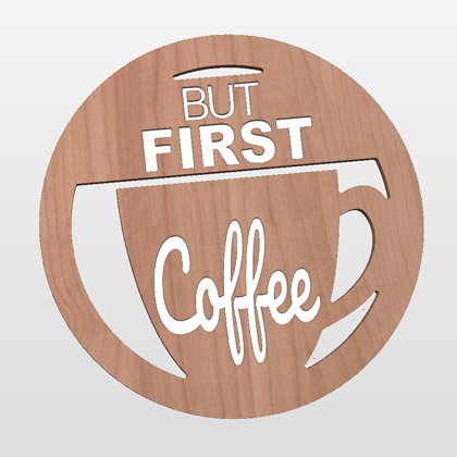
High Quality Toolpath Preview
One of the most important productivity tools available in the software is the realistic 3D toolpath preview support. The results of each individual or the combination of all the toolpaths can be previewed cutting into a 3D preview model. This means that whether your job is a simple toolpath with one tool, or created from a complex combination of tools and strategies at different levels you can be sure that when the job is cut, it is right first time.
As well as showing that the toolpaths are correct, the high quality rendering and ability to use real world material textures and fill colors is a very valuable sales tool. Using the simulation you can create customer proofs and evaluate design options without actually having to cut anything!
Tool Database
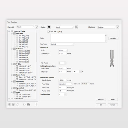
The software has a built in tool database to make cutter management quick and easy. Tools can be organized in any way that suits your workflow. There is automatic support for machine management and material management. Tools can be filtered for your current material and machine settings, which makes selecting the right tool for the job simple. The tool database contains a powerful tool naming system. This allows you to have consistent tool names, and for those tool names to match the properties of your cutter. Your tool database can be synced with your online V&Co account so that changes made to the tool database on one machine can be easily transferred to other running instances. You can share your tool database using a link from your V&Co account. This is particularly useful for users wanting to share their tool data and settings without the end user overwriting their own database.
Online Post Processor and Machine Management
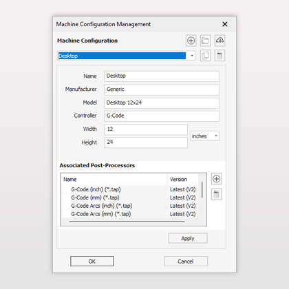
Vectric assists with the management of your CNC machine, its capabilities (for example rotary or laser add-ons), associated post-processors and default tool cutting feeds and speeds for a selection of materials.
As always our software is fully customizable for those who want to have full, low-level, control but Vectric's 'Kickstarter' wizard can help you get started with a set of tools with reasonable initial settings using our constantly updated online list of the most common machine brands and models.
The ‘Kickstarter’ wizard not only ensures that you have the right post-processors and machine configurations straight-away, but the management system also allows you to optionally stay up to date if relevant newer post-processors for your machine are released in the future all from within the software.
Estimated Machining Times
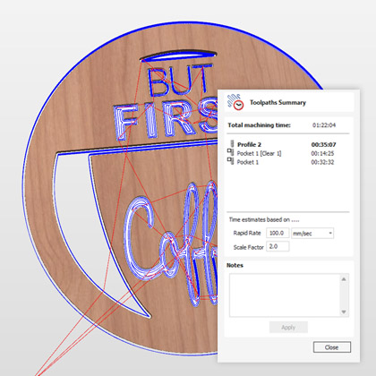
To help estimate how long toolpaths will take to cut the software will calculate a time based on the length of the toolpath and the specified feeds and speeds that have been entered for the selected tool. This can be tweaked by the operator by editing the 'scale factor' so over time a value can be optimized based on actual machine performance to ensure the estimate is as close as possible to the actual cutting time.
Toolpath Tiling – Divides toolpaths to fit material or machine limits
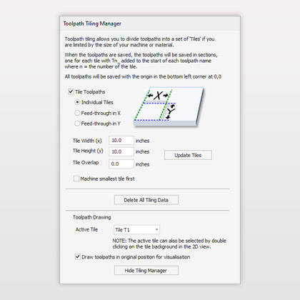
Using the Toolpath Tiling options it is possible to machine objects and designs that are many times larger than the available area of your CNC machine bed. This process is also invaluable if the maximum sizes of your material pieces are limited. In both cases, a much larger project can still be machined by breaking the toolpath down into manageable tiles or strips, each of which can fit within the machineable area of your CNC machine, or on the available material blocks. Once cut, the tiles can then be re-assembled to form the finished piece.
Toolpath Templates
Toolpath templates allow you to improve the efficiency of your production processes by saving the complete toolpath settings for common operations. These settings can then be re-used at any time on different design geometry. Frequently used strategies and tooling can thus be applied to similar jobs, quickly and easily.
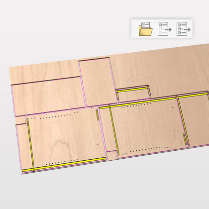
Form Tools - custom shaped cutter profiles
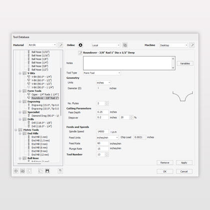
The software allows you to add your own custom tools shapes to the tool library and generate toolpaths and simulate the finished result! Now you can simulate the effects of complex roman ogee cutters, round over bits and any other custom tool shape you desire. Simply draw the tool profile using the vector drawing tools or import the profile from the manufacturer and you can add your custom tool to the list. In the tool database you can specify feed rates, spindle speeds, cutting depths etc. in the same way that you do for any of the standard tool types.
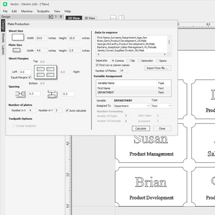
Production Plate Engraving
Production Plate Engraving lets you merge text lists into templates for badges and industrial plates. It can be used to merge CSV and text based lists using variables that can automatically scale to fit a pre-made design layout.
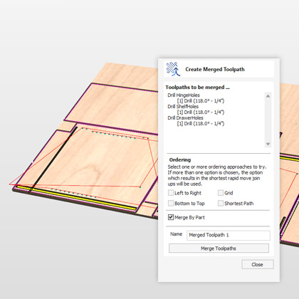
Create Merged Toolpath
The create merged toolpath function allows you to combine toolpaths that use the same tool into a single, new, toolpath that is generally more efficient than cutting the constituent toolpaths independently. This can be particularly useful if you want a complete individual part to be cut before the CNC moves onto the next piece as it can merge the toolpaths into individual components.
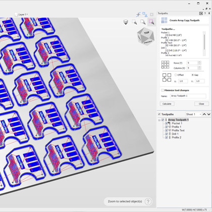
Array Copy Toolpath
Similarly to the area copy tool, this toolpath allows you to duplicate one or more toolpaths (its children) as a block, based on the dimensions you enter in its properties.
Other Features
Other Features
Other Features
Import Toolpaths from other Vectric Programs
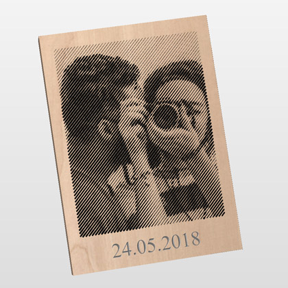
Toolpaths generated in PhotoVCarve can be imported into the software to combine with other toolpath types. Multiple PhotoVCarve projects can be imported and positioned, where additional elements can then be added and machined. All of the toolpaths can then be previewed and saved from the software. Please Note: Photo V-Carving toolpath strategy is included with VCarve Desktop, VCarve Pro and Aspire. PhotoVCarve can also be purchased on its own, for more details see the PhotoVCarve area of the web site.
Printing
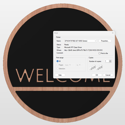
The contents of either the 2D or 3D view can now be printed using the Print command on the File menu. Simply select the view you wish to print (2D or 3D) and then click the Print command. The standard Windows printer dialog allows you to select the printer and adjust its properties. When the OK button in this dialog is clicked, the view will be printed. The Print Preview command on the File menu allows you to check the layout of your page before you print. The printed view is always scaled to exactly fit the currently selected page size (including allowance for margins). Drawings are not, therefore, printed at actual size and are not printed across multiple pages.
File Thumbnails
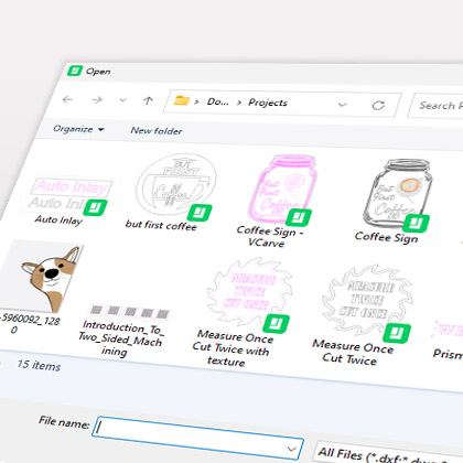
Files saved from the software include a thumbnail image. Windows explorer can make use of these thumbnails to show you a preview of each file when you browse a folder.
Integrated Help
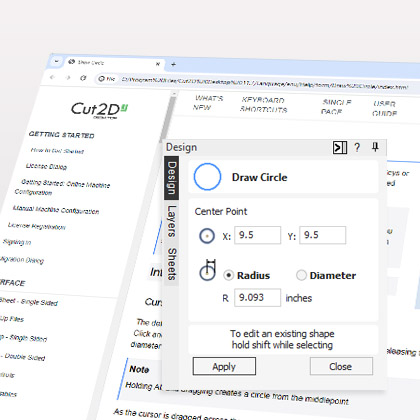
Help for all forms can now be found using the handy integrated help functionality. Click on the question mark icon on the top of each form to get the help for that specific function.
Video Tutorials
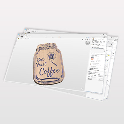
All of our products have in depth video tutorials and data files you need to work through the examples. These are split into sections beginning with getting started projects to let you see the process to produce a complete part and start to understand the general workflow. Then there are videos to cover each area of use within the program. The videos are designed to take you step by step through different types of projects to explain the key methods you will use in the software and to demonstrate these on real-world examples. You can just watch and absorb the contents or follow along pausing where necessary to complete a task. In addition to learning how to use the program the videos include tips and tricks for better use of the software. The result of each project (along with the Clip Art) provides a library of parts which can be machined to create sample files to improve your CNC skills or help you to demonstrate your capabilities to potential customers.
The Vectric Forum
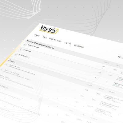
We are very proud of the quality of our software, and maintain an active and open forum at forum.vectric.com. The forum lets users ask questions and discuss techniques related to CNC and the software. In addition to direct input from Vectric, there are a large number of enthusiastic users who are always willing to help on any topic associated with CNC machining. Another very interesting section of the forum is the gallery area where users can post images of projects they have done using Vectric software. Please take a look, there are some very nice examples of work on there.
64-Bit Support
The new versions have installers for both 32-bit and 64-bit computers. The installer will detect and install the appropriate version for your machine. The 64-bit build will enable the software to make use of all the RAM on the PC, this will allow the processing of very long toolpaths, complex nesting jobs and the import and export of very large (STL, OBJ etc.) files.
Pro Edition Features
Pro Edition Features
Pro Edition Features
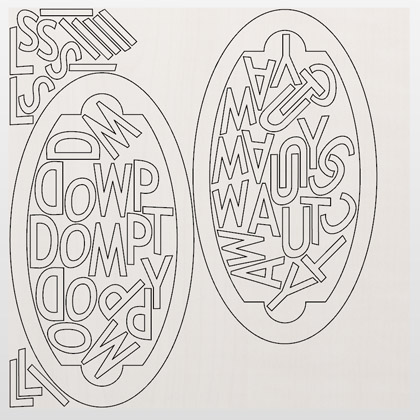
True Shape Nesting
True Shape Nesting lets you automatically arrange and fit vector shapes into your material size or user definable area, to get optimal material usage and minimum wastage. Part Nesting is perfect for Sign and Cabinet makers who need to minimize material wastage and cut as many parts – letters & cabinet doors / panels – as possible from sheet materials. Reduce Material Costs = Increased Profits.
The nesting routine places vector shapes as close to each other as possible ensuring a sufficient gap to allow the parts to be cut out correctly. The nesting includes options to control part direction to reflect material grain or machine orientation. It intelligently determines what parts of your geometry should be nested together. It can also automatically nest objects on both sides of a job together to create two-sided nested geometry.
Create Merged Toolpath
The create merged toolpath function allows you to combine toolpaths that use the same tool into a single, new, toolpath that is generally more efficient than cutting the constituent toolpaths independently. This can be particularly useful if you want a complete individual part to be cut before the CNC moves onto the next piece as it can merge the toolpaths into individual components.

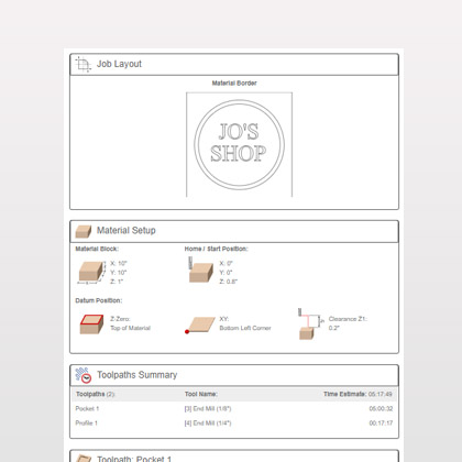
Create Job Sheet
The create set-up job sheet command allows you to create a summary sheet that details all the important information you will need at your CNC machine when you come to run the toolpaths. This can be used as a reference to ensure you have the setup correct, have loaded the correct tool etc. It can also be used to archive with an old job as a quick reference file to see what the job the looked like and the machining that was involved for that project. You can also edit this to change the logo to an image of your own choice, adjust the header, footer and border colours and even customize which sections of information to include.
Toolpath Templates
Toolpath templates allow you to improve the efficiency of your production processes by saving the complete toolpath settings for common operations. These settings can then be re-used at any time on different design geometry. Frequently used strategies and tooling can thus be applied to similar jobs, quickly and easily.

Array Copy Toolpath
Similarly to the area copy tool, this toolpath allows you to duplicate one or more toolpaths (its children) as a block, based on the dimensions you enter in its properties.

No Size Limit
Aspire, VCarve Pro and Cut2D Pro allow you to work with any job size meaning that there are no limitations to the size you want to work with. VCarve Desktop & Cut2D Desktop only support job sizes up to a maximum of 24 inches x 24 inches without tiling. You can cut jobs larger than this limit but you will need to use the toolpath tiling feature to cut the job in sections.
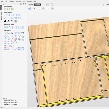
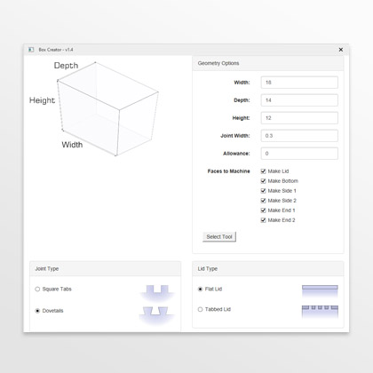
Gadgets
Gadgets are small programs that add additional functionality to Vectric products. They can be used to add new features to the software or automate common sequences of tasks. Examples include adding the ability to cut dovetail style joints with a standard end mill and applying toolpath templates to every sheet in a nested job followed by automatically post-processing and saving the files for your machine tool. You can also associate specific key combinations to these to very quickly access them as part of your standard work-flow. You can browse the gadgets available here.
Online Training Videos
Our online training video's guide you through the process of getting started with our software.
Learn how to use Vectric software in your own time from the comfort of your own home. All of the tutorial videos have been created to enable you to follow along and learn at your own pace.
