
It’s safe to say, the Vectric community never cease to amaze us here at Vectric HQ. We see so many different types of cool projects, but there is one particular type that always grabs our attention. This is exactly what caught our eye when we saw the work of Anthony Hurter...gears!
Gear exposed mechanical objects always get the mind wondering “how was that made?” luckily in this month’s case study Anthony has told us how he went about making this incredible gear clock. Before we get into his creative process, we wanted to ask Anthony about his background…
I am 81 years old, a Mechanical Engineer, and I built up a large company producing alternative hydrocarbon fuels from waste oils. I started with a 3D printer and a Stepcraft CNC three years ago, making prototypes of plant components. I got bored with 3D printing, the Stepcraft was inadequate for what I needed, so I built my own machine.
We wanted to hear what inspired Anthony to create this project and what materials he felt would work best. Here’s what he had to say…
I was looking for an interesting project, clock making fitted the bill. I decided to create a wooden gear clock. To start with I bought 2 wooden clock plans but found that they were insufficient for my ideas, the introduction of Vectric’s Aspire gear making gadget enabled me to design my own clocks, which I was really excited about!
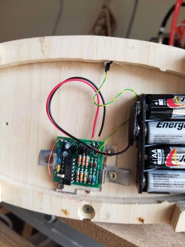
Getting a wooden gear clock to keep time is challenging, but the electromagnetic pendulum drive from Dick Bipes of Carveshop.com solved that problem. This PC board varies the pendulum swing to keep perfect time.
Wood such as Beech and Teak is my first choice, but can be difficult to source in France. I tried Birch ply, but it splintered during machining. A friend I was assisting showed me a part he had cut from Bamboo ply – eureka, material problem solved! Using straight shank 2mm” cutters, the gears turned our great. I bought 10mm bamboo mail order from Amsterdam and some 0.6mm bamboo veneer. The finished veneered and rounded edges are stunning. All a learning process!
Anthony had a good idea by this point of what he wanted to make, aswell as what materials he would need but how did he go about starting his design? Read more to find out…
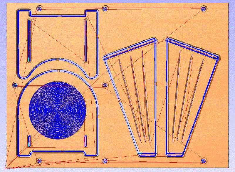
Originally, I designed in the Bricscad (Autocad lookalike) package and transferred the DXF file to Vectric’s Aspire for the tool pathing. But the Aspire package has got so complete now that I can create and toolpath everything in one place.
For the clock project, I do a spreadsheet with the ratios and number of gear teeth. Then from the gear gadget, one gets the PCD and hence the gear centre spacing. Then to the Aspire plan layout, with each component on a new layer. Aspire does not cater for plan and elevation well, but one does a sideways layout alongside the plan.
In the clock projects, most of the machining is with 3.15mm and 2mm straight shank cutters, with profile and pocket toolpaths. Feed rate is set at 2500mm/min, plunge 1200, pass depth 70% of tool diameter (2mm for 3.15 cutter), spindle speed 16000 rpm.
I screw the ply to an 18mm pine spoil board with brass screws. I program in the screws location with 8.5mm 4 deep countersink and 4mm screw hole cut with the 3.15 cutter. In the wine bottle holder project, one uses the fluting too with 4mm ball nose, and the 3.15mm ball nose for the carving.
Ply edges are veneered with 11.5mm wide 0.6mm thick veneer strips, glued with PVA. When set, cut back with a trimming knife and sanded using 150grit sandpaper.
Some projects, I then round the edges with a 3mm radius router. Minimal sanding of the ply surface. Tried using shellac melted in alcohol, with mixed success. In France, one can only buy water-based varnishes, which are a disaster. So now I use Danish Oil – so easy to apply!!
It’s not usually until the projects are completed that you are able to see what you would change if you were to make your project again, but Anthony’s expertise meant that he could see where some of the problem areas might be so he could make a plan in advance…
The gear shaft design from the purchased clock plans were inadequate. So, I started from scratch, and now use 5mm threaded bar for the shafts and 10 x 5 x4 ball bearings. The bearings are a little loose on the shaft, so thread seal tape is used to take up the slack. I use 12mm of copper water tube as a casing, which houses bearings either end. The copper tube is dimpled to retain the outer race. The bearings are spaced on the inner race by 6mm of copper tube, drilled out to 5mm. The 5mm nuts bear on the inner race without fouling the outer race.
Another challenge was the clutch mechanism to permit the minute hand to be moved. The trick here was a felt pad (like one you would use under chair legs) glued to a disc, which is bolted to the centre shaft. The disc presses against the centre wheel with a small spring.
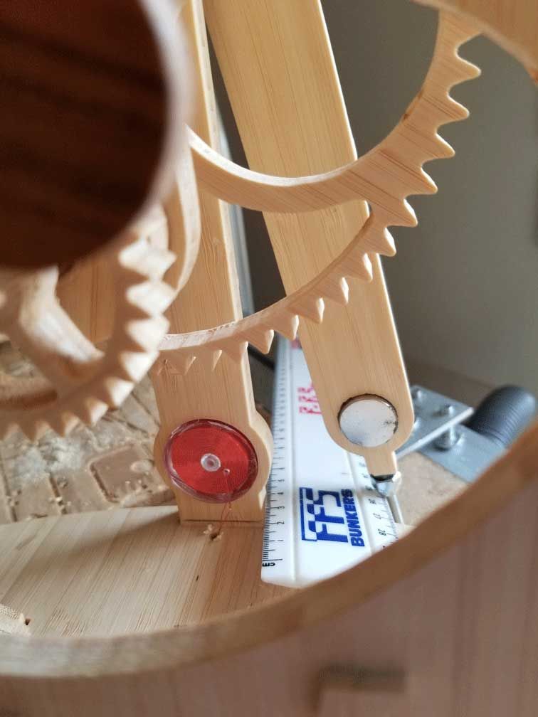
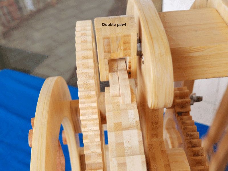
Coping with a variable amplitude swing of the pendulum which drives the ratchet is a problem. Dick Bipes designed a clever cam mechanism which was too challenging for me. I designed a dual pawl system to drive the ratchet wheel, but it is rather difficult to describe it here.
Operating in an apartment requires attention to the noise levels, and dust abatement. Air cooled spindle motors are a no no. I changed to water cooled spindle and operate in the 60 -70dB level inside a double-glazed room. Water cooled spindles can operate at low speeds, great for drilling I have a 0.75 kw Bag filter, and a rectangular 3-part dust duct – a subject for later discussion!!
We wanted to say a huge thank you to Anthony for taking the time to answer our questions and write up his projects so that we could inspire our community to try something new. Anthony’s hard work has clearly paid off as he has some amazing projects already. Before we let him go, we asked Anthony what plans he had for the future…
Lots! Provide my health and brain will allow me! Wine bottle stands make for great dinner party gifts. My son wants new architraves, should be a doddle with the Architectural clipart. I have not yet got my head around turning, and wood engraving looks fascinating, but that’s probably beyond my league so we’ll see.
To purchase plans to create your own clocks like this head over to: Lisaboyer.com

Vectric Ltd
Precision House
2 Arden Road
Alcester
B49 6HN
Registered in England Number 05382596
VAT Registration GB115123072
Privacy Policy |
Cookie Policy |
Terms and Conditions


